Stress and strain are commonly used mechanical parameters in engineering. By measuring the strain and stress of mechanical parts and structures, it is possible to analyze the stress and working conditions, verify design calculations, and determine the working process and the mechanism of certain physical phenomena.
Problems in current strain measurement
1) Matching of measuring point info. and channels
The following conditions are often encountered during strain measurement.
● In the testing process, it is necessary to record the measuring point location, the cable, the channel, the instrument No., the cabinet No. and other parameters separately. The process is cumbersome and monotonous. Once there is a link error, it is not easy to troubleshoot;
● If one link is damaged in the above processes, the entire relationship line need to be tracked and recorded.
If the whole test has not been completed on the first day, the staff need to recover the on-site collection devices by separating the signal line and the instrument. The common way is to mark each signal line and match them one by one on the second day. However, there are thousands of lines and cables, it is not convenient for the staff to do this work. Therefore, it is urgent to find out a method that can bind the measurement point information and the instrument.
2) Influence under the condition of long wire
For the strain measurement, the influence of the long wire must be taken into account. The actual calculation of the software is based on the bridge voltage inside the instrument, but the long wire will cause a pressure drop at both ends of the strain gauge, and the measured strain value will be smaller .
There are many ways to eliminate the influence:
● Manually measure the wire resistance, and input the value into the software to deduct the influence during the strain calculation;
● Measure wire resistance through the hardware circuit, and automatically input the value into the software to deduct the influence during the strain calculation
● Directly input the bridge voltage to both ends of the strain gauge to eliminate the influence;
● Through constant current excitation, convert the change of resistance into the change of strain to eliminate the influence.
3) High temperature causes dramatic changes in resistance
In high-temperature strain measurement, the resistance value of strain gauge will change with the change of temperature. The change may exceed the range of bridge circuit, which will cause the traditional Wheatstone bridge to be unbalanced and unable to measure.
The figure below is a Wheatstone bridge. Eo is the output voltage, Ei is the supply bridge voltage, and the output voltage changes with the change of bridge arm resistance. As is shown in equation (1), ΔR<<R, so the higher-order terms of ΔR in denominator and ΔR in molecule can be ignored. Then it can be simplified to equation (2) for the most commonly used equal-arm bridge.
In high-temperature test, ΔR cannot be ignored, so the high-order terms cannot be ignored, and nonlinear effects need to be considered. Therefore, common Wheatstone bridge will bring errors in strain measurement.
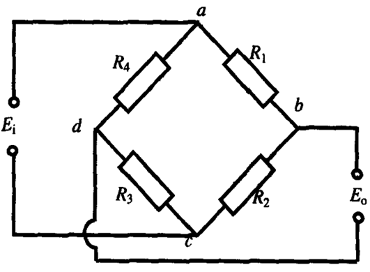
Figure 1- DC bridge

Equation (1)

Equation (2)
4) Check the channel status
Before strain measurement, it is necessary to check whether there is a problem in the bridge. Usually, the test engineers will tap measuring points one by one to check the strain change, but sometimes there would be too many measuring points that are not easy to tap. Thus, a simple and fast way is needed to detect all channel status.
5) Periodic calibration of channels
It is required to regularly calibrate the accuracy of strain measuring instruments which are usually sent to the local metrological service. If there is a multi-channel parallel calibration system, it will make strain measurement easier.
Solutions
A. Intelligent recognition of measuring points and sensors
As long as the user-defined measuring point information is bound to the wire number, the system automatically reads the measuring point information and always corresponds to the data. At the same time, the intelligent wire also saves the hardware’s measuring point parameters, which can automatically enter the parameter information of the measuring points after changing the channel. Thus, this function is able to improve the work efficiency and avoids on-site errors.
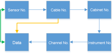
Figure 2
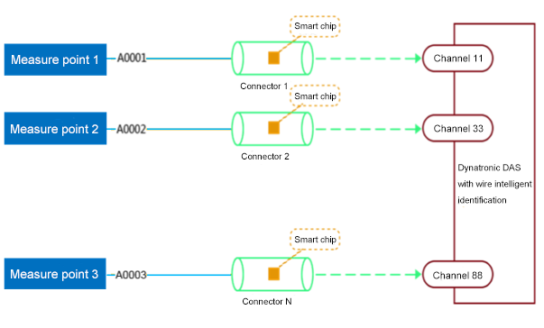
Figure 3
B. Automatic measurement and correction of wire resistance
This function enables the users to complete the automatic measurement of long wire resistance in the state of 1/4 bridge (three-wire system), half bridge and full bridge by just one click, at the same time, correction will be done automatically according to different working state.
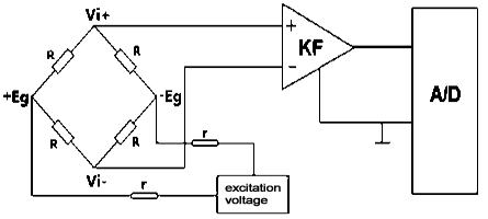
Figure 4
C. Four-wire supply bridge and double constant current excitation
1) The four-wire supply bridge technology is used to ensure that the reference voltages at both ends of the sensor are stable, so that there is no need to worry about the voltage change due to the long distance of the measuring point.
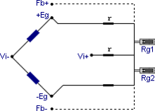
Figure 5
2) Using symmetrical constant current excitation technology is the best way to measure data with strain gauges at high temperature. Symmetrical excitation ensures that the amplifier’s common-mode rejection (CMR) provides high noise immunity to allow the same strain gauge to measured static and dynamic data.
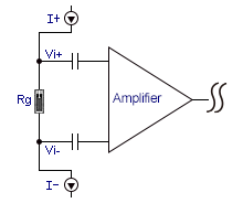
Figure 6
D. Self-check system
Self-check system can synchronously completes self-checking of all states of all channels (including bridge voltage, bridge connection, amplifier, automatic balance, A/D converter and sampling control, etc.) by just one click.
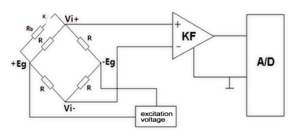
Figure 7
E. Strain programmable automatic calibration function
A single program-controlled standard strain source can simultaneously complete 16 (full bridge, half bridge, 1/4 bridge) strain indication error and strain nonlinear error. Multiple sources can be calibrated online at the same time to realize intelligent one-button strain calibration and quick start. This calibration function can save a lot of time and effort without manual intervention, and also it can automatically generate reports.
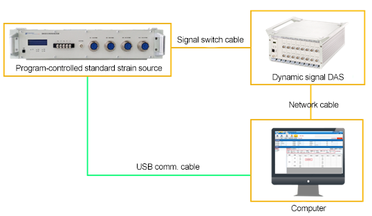
Figure 8