Generally speaking, there is often a distance of tens or hundreds of meters between the measuring point and the measuring instrument in the field test. Thus, the two-wire connection method is considered from the perspective of costing and wiring difficulty.

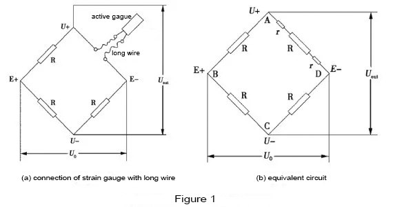
Figure 1 is the connection and equivalent circuit of a single strain gauge with long wire. In this figure, “r” is the resistance of long wire. The balance range of the strain instrument is generally less than ±2% of the bridge arm resistance, that is, 2r≤±2%R; when the short wire is connected, the “r” value is small, so it does not affect the balance.
Name the vertices of the bridge circuit in the Figure 1-b as A, B, C, and D. When the active gauge is not stressed, the voltages of the bridge arms AD and CD are respectively as follows:

The bridge output voltage is:


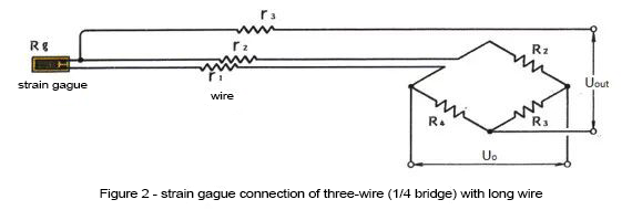
In order to reduce the influence of wires, a three-wire system can be used. As is shown in Figure 2, connect another wire to one of the strain gauge wires, and use 3 wires to make the bridge longer. The difference between this connection and the two-wire system is that the wire resistance is shared by the adjacent two sides of the bridge.
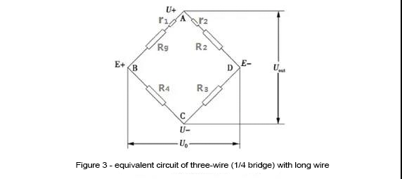
Figure 3 is the equivalent circuit of three-wire (1/4 bridge) with long wire. The wire resistance r1 is connected in series with the strain gauge resistance Rg, r2 is connected in series with R2, and r3 becomes the output of the bridge.

Due to the introduction of long wire resistance, the three-wire connection effectively solves: a) the problem of strain gauges cannot be balanced during single-arm measurement; b) the output problem of offsetting the thermal effect of long wires.
When the ambient temperature of the test site changes greatly, the three-wire connection cannot eliminate the output of the strain gauge thermal effect caused by the ambient temperature, then, half-bridge wiring is required.